Automatic Street Light Control Circuit Using Ldr Transistor

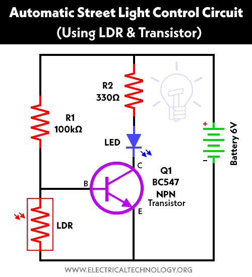
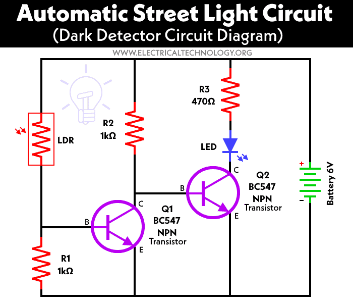
Automatic Street Light Control Circuit Using Ldr Transistor Automatic street light control system using ldr and two nos. of transistor bc 547. whenever light falls on the ldr (light dependent resistor), the led is off i.e. the led does not glow. in the dark (e.g. when light is blocked to the ldr), the led is on i.e. the led is on. snapshot taken out from the video. So here in this project, we are going to make a simple automatic street light circuit using ldr and relay, which will turn on and off the light bulb based on the lights in surroundings. this circuit is quite simple and can be built with transistors and ldr, you don’t need any op amp or 555 ic to trigger the ac load.

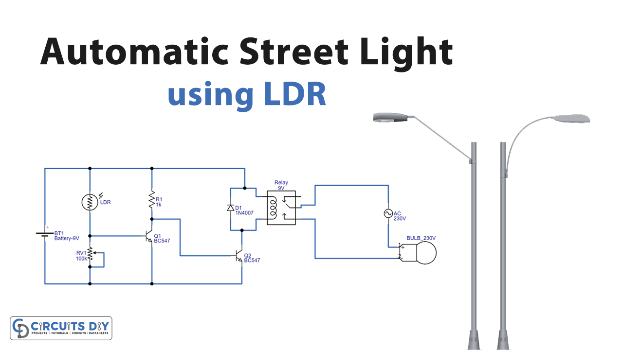
Automatic Street Light Controller Using Ldr Working of automatic street light controller switch circuit. the working of circuit is very much easy to understand. in this circuit, we used ic lm358, which is basically an operational amplifier. pins 2 and 3 of these ic are used to compare the voltage and give us an output as high or low depending on the voltages at the input pins. This automatic street light controller circuit using ldr involves in handling of high voltage ac supply, handle with extreme care. ldr or photoresistor is the sensor here and the variation in the resistance converted into relay switch turn on and off position through two transistors. ldr is connected between bias lines through variable resistor. The circuit diagram represents a simple automatic street light control system using transistors and a light dependent resistor (ldr). here is an explanation of its working: ldr: the ldr is a light sensitive resistor that changes its resistance based on the intensity of light falling on it. when the light level is high, the resistance of the ldr. Step 2: start building on tinkercad. the components you will need to add include: 9v battery. npn transistor (has a collector, base, and emitter. electricity will flow to the collector, and will only flow out of the emitter when the base is given electricity.

Automatic Street Light Control Circuit Using Ldr Transistor The circuit diagram represents a simple automatic street light control system using transistors and a light dependent resistor (ldr). here is an explanation of its working: ldr: the ldr is a light sensitive resistor that changes its resistance based on the intensity of light falling on it. when the light level is high, the resistance of the ldr. Step 2: start building on tinkercad. the components you will need to add include: 9v battery. npn transistor (has a collector, base, and emitter. electricity will flow to the collector, and will only flow out of the emitter when the base is given electricity. In this circuit of automatic street light controller using ldr, when the light falls on ldr it becomes an element that is less resistive and therefore allows bias to appear at transistor q1 base. it turns on the transistor q1. since there is no bias at the base of transistor q2, therefore it remains off. in this condition, the relay coil is not. Place the transistor on the breadboard. connect the emitter to the negative of the battery. base to one terminal of ldr. connect the resistor (r2) to base and positive terminal of battery. collector to the anode of led (small leg) from cathode of led (long leg) to resistor (r1) another end of resistor (r1) to positive terminal of battery.

Comments are closed.