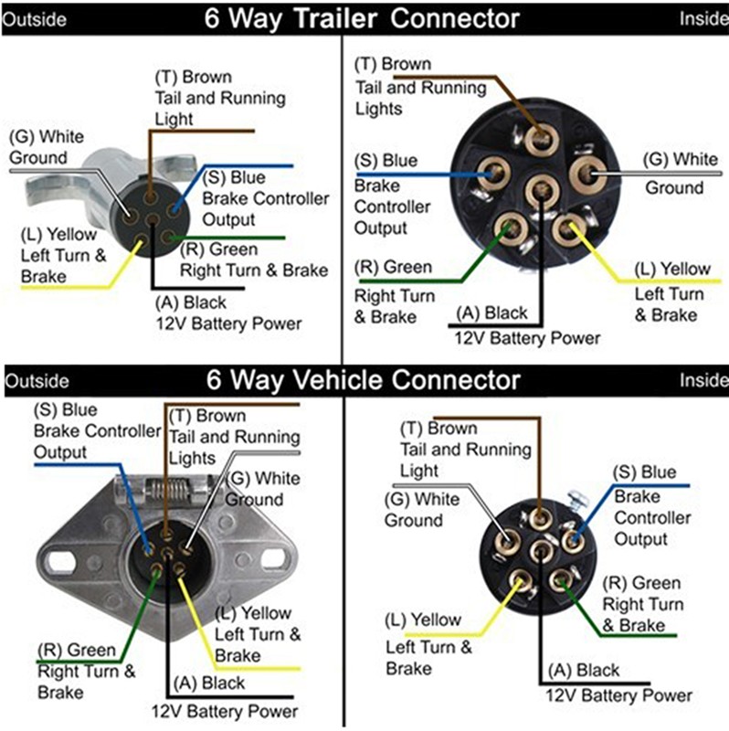
7 Pin Trailer Light Wiring Diagram
7 Way Trailer Plug Wiring Diagram With Brakes The minimum suggested wire size for a 7 way trailer plug is 16 gauge for the turn signals, brake lights, reverse lights, and running light wires. the suggested minimum for the ground, brake power, and battery hot lead wires is 12 gauge. if the wire is too thin, it can overheat and even catch fire when carrying electrical current. The 7 pin trailer plug is the most common type used for connecting trailers to vehicles, providing all the necessary signals for lights, brakes, and other electrical components. in this comprehensive guide, we will walk you through the complete wiring diagram for a 7 pin trailer plug, making installation a breeze.

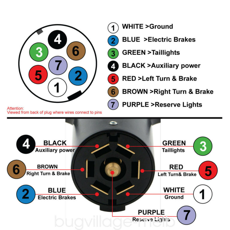
7 Pin Flat Trailer Plug Wiring Diagram 7 pin trailer wiring diagrams. below are the 7 pin trailer wiring diagrams for each of the three main types of trailers. even if your wiring color codes do not match up with that of the universal color coding listed earlier, the functions of each of the wires (regardless of color) will still match up with the same pins in the wiring diagram. A trailer lights wiring diagram 7 pin is a visual representation of the electrical connections needed to operate the lights on a trailer. it shows how the seven pins on the trailer plug are connected to the corresponding wires on the towing vehicle, allowing for the transmission of power and signals to control the trailer lights. The wiring diagram for a 7 pin trailer connector is an essential tool for ensuring proper installation of the electrical connections between a tow vehicle and a trailer. the 7 pin trailer connector is commonly used for towing trailers with electric brakes or for powering various accessories on the trailer, such as lights and brake controllers. The seven pins in a trailer plug are labeled with numbers or letters for easy identification. here is a breakdown of the pin configuration: pin 1: this pin is used for the left turn signal or indicator lights. it connects to the corresponding wire on the towing vehicle. pin 2: the second pin is for the reverse lights.

7 Pin Trailer Connector Wiring Diagrams The wiring diagram for a 7 pin trailer connector is an essential tool for ensuring proper installation of the electrical connections between a tow vehicle and a trailer. the 7 pin trailer connector is commonly used for towing trailers with electric brakes or for powering various accessories on the trailer, such as lights and brake controllers. The seven pins in a trailer plug are labeled with numbers or letters for easy identification. here is a breakdown of the pin configuration: pin 1: this pin is used for the left turn signal or indicator lights. it connects to the corresponding wire on the towing vehicle. pin 2: the second pin is for the reverse lights. Step 3: test connections. before sealing everything, conduct a thorough test. connect the trailer plug to the vehicle's socket and check if all lights and functions are working correctly. test the tail lights, turn signals, brake lights, and any other accessories connected to the plug. Pin 5: electric brakes (blue wire) pin 6: auxiliary charge line (red or orange wire) pin 7: backup lights or auxiliary (purple wire) by following the 7 pin trailer plug wiring diagram, you can easily connect your trailer to your vehicle and ensure that all the necessary electrical functions are working correctly.

Wiring Diagram For Trailer Lights 7 Pin Step 3: test connections. before sealing everything, conduct a thorough test. connect the trailer plug to the vehicle's socket and check if all lights and functions are working correctly. test the tail lights, turn signals, brake lights, and any other accessories connected to the plug. Pin 5: electric brakes (blue wire) pin 6: auxiliary charge line (red or orange wire) pin 7: backup lights or auxiliary (purple wire) by following the 7 pin trailer plug wiring diagram, you can easily connect your trailer to your vehicle and ensure that all the necessary electrical functions are working correctly.

Wiring Diagram For Trailer Lights 7 Way Shelly Lighting

7 Pin Trailer Light Wiring Diagram

Comments are closed.