3 Pin Computer Fan Wiring Diagram

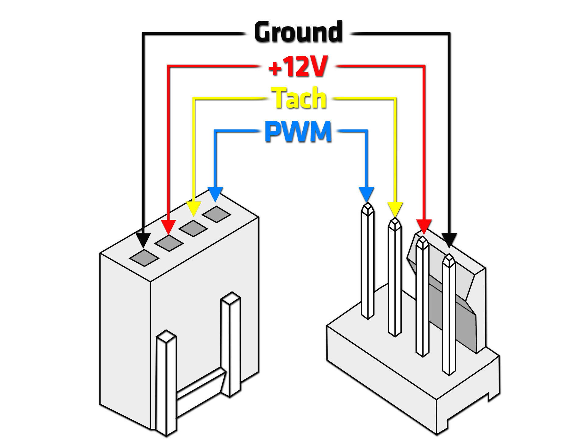
3 Pin Computer Fan Wiring Diagram In this article, we will delve into the basics of a 3 pin fan wiring diagram and explore how it works. a 3 pin fan is a type of cooling fan commonly used in computers. it consists of three wires: the positive ( ) wire, the negative ( ) wire, and the sensor wire. the positive wire supplies power to the fan, while the negative wire is connected. 3 pin and 4 pin fan wire diagrams. 3 pin fan connections. *cable coloring varies from fan to fan. pin name. color. color. color. color. 1.

3 Pin Pc Fan Wiring Diagram Diysish 1. identify the three pins: the first step is to identify the three pins on the fan connector. the pins are usually labeled as “gnd” (ground), “ 12v” (power), and “sig” (signal). it’s important to correctly identify each pin, as connecting them in the wrong order can cause damage to the fan or the connected device. 2. 3 wire pc bldc fan. input voltage: 12vdc ±10%. peak current (@12vdc): 200ma. tachometer output: 2 pulses per revolution (open collector drain output) and then what i’ve observed is a clumsy tacho output signal, it’s natural just because there’s no pull up resistor added at the output. so i added one 10kΩ pull up resistor, and a 100nf. Not all fans or motherboards control or power the fan assemblies the same way. fans may be either 5 volt dc or 12 volt dc fans. colors may change. chassis and cpu fans may use either 3 pin or 4 pin power connectors. 3 pin connectors are usually used for the smaller chassis fans with lower power consumption. 4 pin connectors are usually used by. 1. the fan connector will have two guides (1) and these will need to line up with the tab (2) that is on the motherboard fan header. 2. next, press down until the fan connector is fully connected to the motherboard header. please note: you can connect a 4 pin fan to a 3 pin or 4 pin header on the motherboard.

3 Pin Computer Fan Wiring Diagram Not all fans or motherboards control or power the fan assemblies the same way. fans may be either 5 volt dc or 12 volt dc fans. colors may change. chassis and cpu fans may use either 3 pin or 4 pin power connectors. 3 pin connectors are usually used for the smaller chassis fans with lower power consumption. 4 pin connectors are usually used by. 1. the fan connector will have two guides (1) and these will need to line up with the tab (2) that is on the motherboard fan header. 2. next, press down until the fan connector is fully connected to the motherboard header. please note: you can connect a 4 pin fan to a 3 pin or 4 pin header on the motherboard. A 3 pin fan is a common component in computer systems and electronic devices that requires cooling. understanding the wiring diagram of a 3 pin fan is essential for troubleshooting and customization purposes. a 3 pin fan typically consists of three wires: the ground (gnd) wire, the power (vcc) wire, and the tachometer (tach) wire. Section 1: understanding the basics of pc fan wiring. in order to properly wire a pc fan, it is important to understand the basics of how the fan functions and the different components involved. a pc fan is typically composed of four wires: two for power and two for control. these wires are used to power the fan and regulate its speed. the.

3 Pin Computer Fan Wiring Diagram A 3 pin fan is a common component in computer systems and electronic devices that requires cooling. understanding the wiring diagram of a 3 pin fan is essential for troubleshooting and customization purposes. a 3 pin fan typically consists of three wires: the ground (gnd) wire, the power (vcc) wire, and the tachometer (tach) wire. Section 1: understanding the basics of pc fan wiring. in order to properly wire a pc fan, it is important to understand the basics of how the fan functions and the different components involved. a pc fan is typically composed of four wires: two for power and two for control. these wires are used to power the fan and regulate its speed. the.

3 Pin Computer Fan Wiring Diagram

3 Wire Computer Fan Wiring Diagram

Comments are closed.